
Movement of the X-shift and Y shift controls allows horizontal and vertical movement of the spot. Set up the Kikusui oscilloscope controls as follows: Note that some of the basic functions of the scope are described in Section III.1 of the "Introduction to Electronic Experiments" section. The display system is a screen coated with a fluorescent material or phosphor which, when struck by the electron beam, emits visible light.Ģ.1 Application of a p.d. The displacements caused by the X and the Y plates may be considered independent. The deflection system comprises the X plates and the Y plates: two sets of parallel plates so arranged that the field created between opposite plates causes a corresponding deflection of the electron beam. (iii) the focusing and final anodes, the combined electric fields of which focus the beam to a fine point on the screen. (ii) a grid whose potential is made negative with respect to the cathode and whose function is to control the electron flow (thus controlling the display brightness) and (i) a heated cathode which emits electrons that are drawn to the first anode,

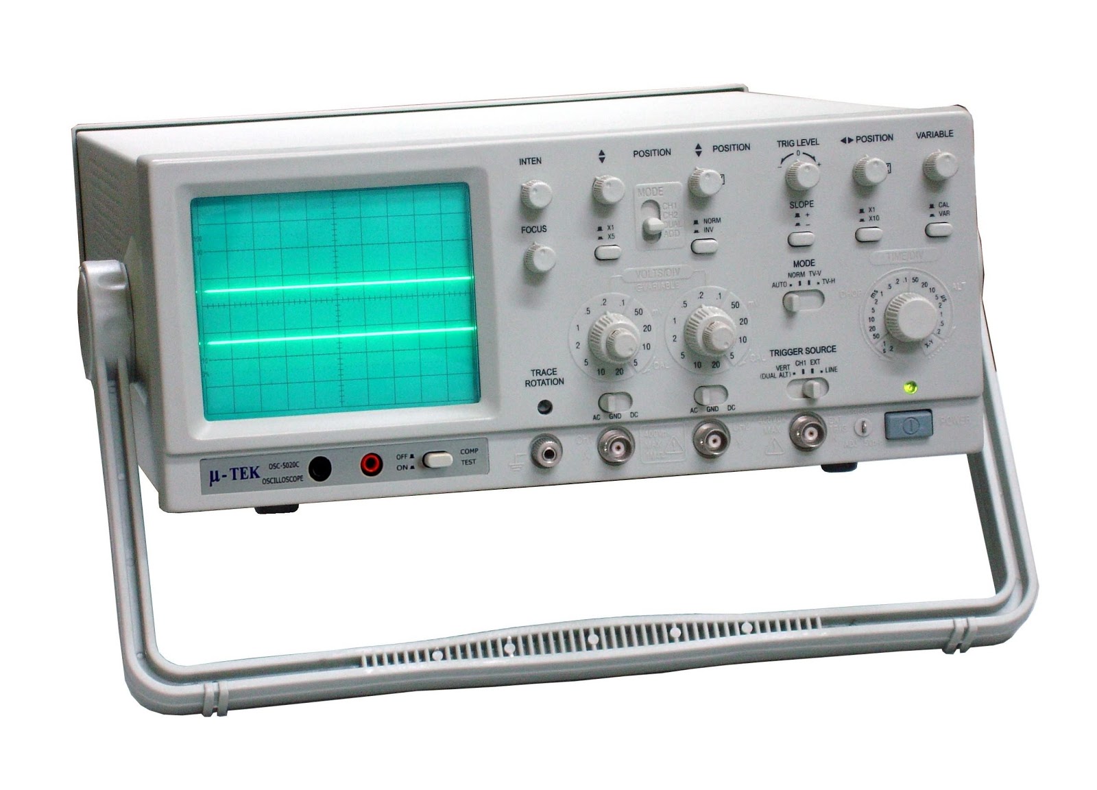
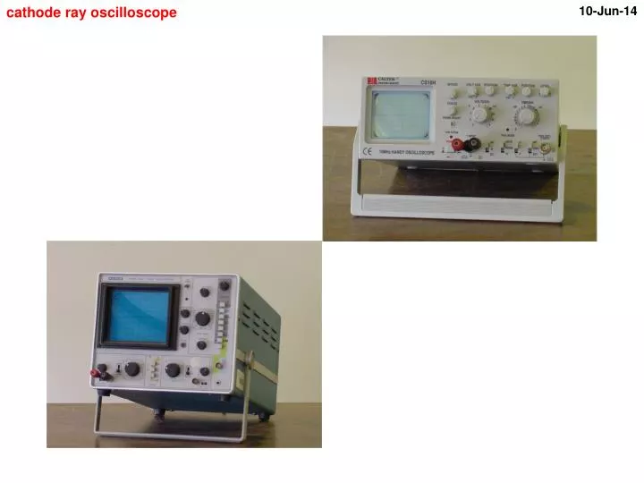
In its simplest form, the cathode ray oscilloscope (CRO) consists of an electron gun, a deflection system and a display system (as shown in Figure 4.1).įigure 5.1: Schematic diagram of cathode ray oscilloscope In addition to the amplitude of the signal, an oscilloscope can show distortion, the time between two events (such as pulse width, period, or rise time) and relative timing between two signals. Oscilloscopes are commonly used to observe the exact wave shape of an electrical signal. Special-purpose oscilloscopes may be used for such purposes as analyzing an automotive ignition system, or to display the waveform of the heartbeat as an electrocardiogram.Īlthough an oscilloscope displays voltage on its vertical axis, any other quantity that can be converted to a voltage can be displayed as well. General-purpose instruments are used for maintenance of electronic equipment and laboratory work. Oscilloscopes are used in the sciences, medicine, engineering, and telecommunications industry. To determine the I V characteristics of a diode.įamiliarisation with electrical prototype boards and multimeters. To determine the I V characteristics of a resistor. In the second part of the experiment, you will determine the I-V characteristics of a diode and resistor.Īn introduction to using an oscilloscope. The purpose of the first part of this experiment is for you to gain familiarity with such a useful piece of equipment. It allows observation of constantly varying signal voltages, usually as a two-dimensional graph of one or more electrical potential differences using the vertical axis, plotted as a function of time on the horizontal. Experiment 5: The Cathode Ray Oscilloscope and Circuit Constructionīefore attending the laboratory you are recommended to read the "Introduction to Electronic Experiments", section III.1, for additional information on the equipment that will be used.Ī cathode ray oscilloscope (CRO) is a common piece of electronic test equipment.


 0 kommentar(er)
